
- Arduino usb logger install#
- Arduino usb logger serial#
- Arduino usb logger code#
- Arduino usb logger Pc#
The LCD pin corresponds to the Arduino pin below it.
Arduino usb logger code#
Here is a table for where each lcd pin goes for my code to work. But the arduino pins that the data logger use are marked also. Here are some ideas if you want to build an Arduino data logger with or without a PC. However, it does not have a built-in method for saving the data.

Arduino usb logger serial#
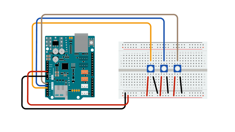
It is drawn as if you are using the stackable header pins. The Arduino serial monitor is usable when you want to watch data from an Arduino. Here is the wiring diagram for my data logger. you can solder wires to the board or follow my pictures.ģv, 5v, Gnd, A4, A5, 13, 12, 11, 10. These are the pins that are needed for the SD card to work. If you have the stackable header pins on the data logger then skip this step. Press Switches (x2) for screen dimming and recording on/off. Sensors: Voltage, Current and Photoresistor. It is short for Secure Digital, and is a great option for storing large quantities of data. You have most likely used, nevertheless heard, of the SD card. The data logger can manage input current up to 5A and between 0 and 20V. A formatted micro SD card (with adapter). If you don’t want to buy the stackable header pins for the Datalogger shield you can use some way like how I modified the Datalogger shield in step 2 so that it could be placed in the bread board.Īnalog Temperature sensor Step 2: Modify the Data logger Power is provided by any USB battery pack. From my experience if your trying to follow instructions while learning and are using different parts it is much harder. Either from the data being collected (green background for nominal values, red for warning), or through the use of a button. have the background color of the screen change somehow.
Arduino usb logger Pc#
After that, we will access this file from a PC and create a chart of. Then we will store these values in the SD card file using the mini SD card Module.
Arduino usb logger install#
My intention is to install the drivers on my Windows 10 machine and connect some sort of USB data logger between the computer and the badge to record the protocol and data transmissions in both directions. I'd like to have the option to use one as a display for an Arduino project.


 0 kommentar(er)
